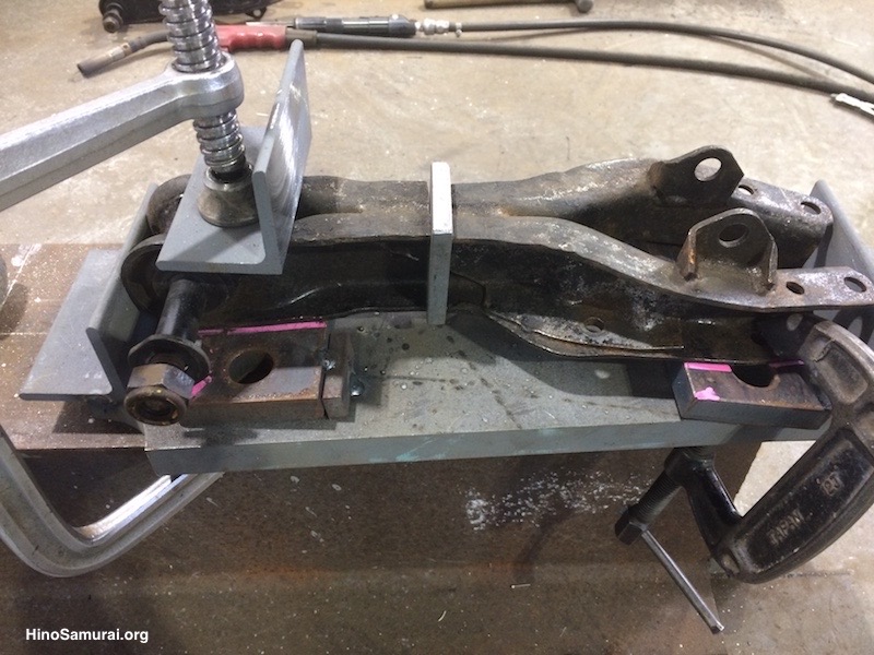
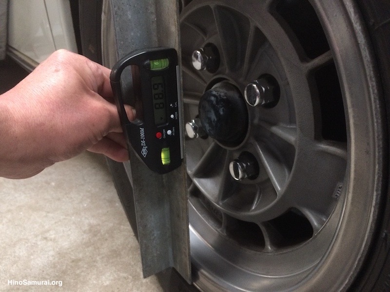
前輪、キャンバーの調整&補正。日野の整備書によれば、基準値は1.3度、これはあくまで当時の設計、あるいはバイアスタイヤの時代の産物。同書によれば、ロアアーム・サポートを基準に3ミリの調整でおよそ1度のキャンバー角の補正になる。
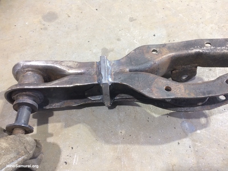
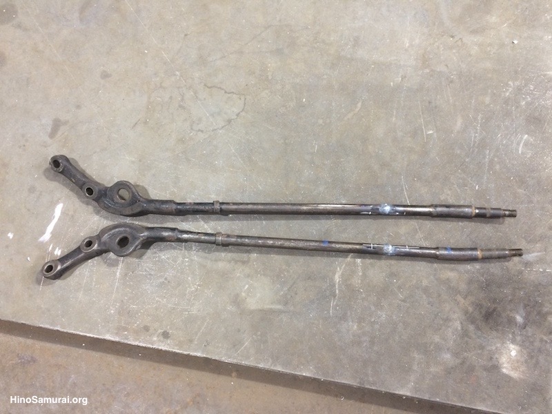
まずアッパーアームに所定の厚さの鉄板をかまし、溶接し、必要な長さにする。
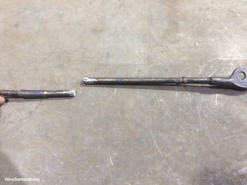
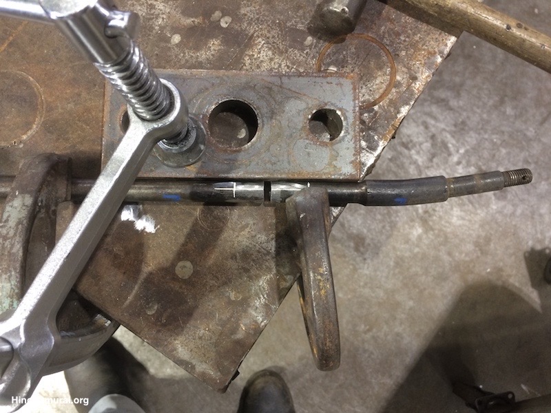
次のテンションロッドを同様に長さの補正をする。テンションロッドの構造自体が数個の溶接の組合わせ品。
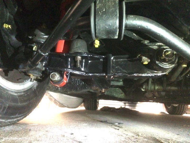
ペイント後、組付け。おそよ1度弱の目論んだネガティブキャンバーが完成!この後、トーイン&アウトの調整。
本ページへのコメント&意見はこちら迄 (実名表記にて) 。
Any Comments to here would be appreciated (Please Use your one name)